
CNC Precision Milling
CNC Precision Milling — Ra and Rz controlled from Dongguan, ±0.003 mm, CMM-verified. Tolerances: ±0.003 mm milling, ±0.002 mm turning — ISO 9001 / IATF 16949 verified.
CNC precision milling is decided by surface finish and rigidity as much as spindle power. This page covers Ra and Rz, workholding, and what chatter does to a precision part.
What is CNC precision milling?
CNC precision milling is milling held to tight tolerances and controlled surface finish — Ra and Rz values you can specify and check. Finish and rigidity decide more than spindle power: a workholding setup that flexes will chatter the tolerance away.
A fine machined finish is not produced by a more expensive machine. It is produced by decisions made at the tool and the setup, long before the spindle spins. The three that matter most:
- Cutting parameters. Feed rate, spindle speed, and depth of cut set the texture left behind by each pass. A finishing pass runs light and fast enough to shear the material cleanly rather than tear or rub it.
- Cutter selection and condition. A sharp, properly coated end mill with the right geometry for the alloy cuts a smoother surface than a dull or generic one. Cutter wear shows up on the surface before it shows up in the dimension.
- Rigidity of the whole system. If the tool or the part flexes even a few microns during the cut, the finish shows it as visible ripple. This is why finish and workholding are the same problem solved twice.
Behind all three sits a quieter variable: how the shop sequences its passes. A typical precision part is roughed first — heavy cuts that remove the bulk and leave a deliberately coarse surface — and then finished with light, clean passes that shave the last few tenths. Running a finish pass on top of a rough cut without changing the tool or the parameters is how a shop gets a surface that looks fine in a photo but measures poorly under a profilometer.
The result is graded numerically, not by eye. Surface finish is quantified as roughness, measured in microns, and the two numbers you sees most often are Ra and Rz. The exact level a part needs is set by what the surface does, not by a number picked from a table. Tell the supplier what the face must do — seal, slide, locate, or simply look clean — and let the process be chosen to match.
What do Ra and Rz actually measure, and which number does each surface need?
Roughness is the fingerprint of the cutting process, and it is read in two common scales. Ra is the arithmetic average of how far the surface deviates from its mean line over a sampled length — a single number that summarizes overall texture. Rz is the average peak-to-valley height over the same length, which captures the worst excursions a gasket or bearing must contend with. A surface can share the same Ra as another and still differ in Rz, because Rz is sensitive to the occasional deep scratch that Ra averages away.
As a rough rule of thumb for a machined profile, Rz runs several times the Ra value, but the exact ratio depends on the profile shape, so the two are not freely interchangeable. A drawing should name one scale and stick to it, rather than mixing them and leaving the shop to guess.
| Roughness (Ra) | Typical production | What it suits |
|---|---|---|
| 0.4 µm | Ground / honed / lapped | High-pressure seals, precision bearing journals, optical faces |
| 0.8 µm | Fine ground or fine milled | Bearing seats, dynamic seals, sliding surfaces |
| 1.6 µm | Fine milling / turning | General sealing faces, locating surfaces, mating flanges |
| 3.2 µm | Standard machining | Non-critical faces, structural surfaces, cosmetic covers |
| 6.3 µm | Rough machining | Clearance surfaces, stock for later finishing |
Read the table as a cost ladder, not a menu. Every step down in Ra costs more machining time, a sharper tool, and a more rigid setup. A buyer who writes "0.4 µm everywhere" multiplies cost on surfaces that only needed 3.2 µm. The right move is to put the fine number only where the surface does work — the seal, the bearing, the sliding face — and let the rest default to a standard machined texture. That single decision is one of the largest cost levers in precision milling.
One practical note on reading a drawing: when a callout says only "Ra 0.8" without a scale name, it is almost always Ra in micrometres, but confirm it, because a missing unit is exactly the kind of ambiguity that produces a beautifully machined surface at the wrong roughness. And when a surface needs to be flat and smooth — a vacuum seal, a thermal interface — the roughness number is only half the story; flatness is a separate callout, and a surface can be smooth and still not flat. Finish, flatness, and dimension are three different tolerances that ride on the same face.
Why does workholding rigidity matter more than the machine brand?
Accuracy is a chain, and the chain breaks at its weakest link. The links run: machine frame, spindle, toolholder, cutter, workpiece, fixture, table. A shop can own a top-tier machining center and still ship out-of-spec parts if the workpiece is clamped in a way that lets it flex or shift under cutting load.
Think of it as a lever problem. Every cut pushes back against the part. If the part is held with a long overhang, a thin wall, or a soft, springy setup, the cutting force bends it. The cutter then removes material from a part that is not where the controller thinks it is, and when the clamp releases, the part springs back to a shape that is no longer to print. The dimension was right on the machine and wrong on the bench.
This springback is the single most common way a machined part fails tolerance even though the machine did exactly what it was told. It is also invisible to the operator who watches the screen, because the controller reports where it commanded the tool to go, not where the material actually ended up. The only defense is to make the setup so stiff that the deflection never rises above the tolerance band in the first place.
This is why serious precision work uses purpose-built fixtures, full-depth clamping, and short, stiff tool assemblies. The goal is not just to hold the part — it is to hold it so rigidly that the part and the cutter behave like one solid body during the cut. Rigidity, not horsepower, is what buys a micron.
There is a second-order effect here that buyers miss: rigidity is also what lets the shop run faster. A stiff setup can take a heavier cut and a faster feed without the part moving, so the same part machines in less time and with fewer scrapped attempts. A shop that fights a flexible setup spends its time re-clamping, re-cutting, and chasing a dimension that keeps moving. The rigid setup is not the expensive option — it is the one that makes the tolerance achievable at a sane price. This is why the workholding question belongs in every sourcing conversation, not just the tolerance one.
What does vibration and chatter do to a precision-milled part?
Chatter is the failure mode that ties the whole topic together. When the cutting force excites a natural frequency in the tool or the workpiece, the system oscillates. The cutter no longer slices cleanly — it bounces off the surface, leaving a distinctive wave pattern, dulling or chipping the cutting edge, and drifting the dimension as the oscillation grows.
Chatter ruins a part three ways at once: the surface finish is destroyed, the tool wears or breaks prematurely, and the dimension drifts outside the tolerance window as the setup moves. It is also self-reinforcing — the rougher the surface becomes, the worse the next pass behaves.
Every setup has one or more natural frequencies, set by the mass and stiffness of the machine, the toolholder, the cutter, the fixture, and the part itself. Chatter starts when a cutting parameter lines up with one of those frequencies and feeds energy into it instead of dissipating it. The fix is rarely "slow down and hope" — it is to change the stiffness or the mass of the weakest link so the resonant condition stops being met.
Suppressing chatter is a matter of removing the flexibility that lets it start. Stiffer tooling, shorter overhangs, rigid fixtures, and cutting parameters that stay away from the resonant speed of the setup all do the job. A shop that understands chatter does not chase it after it appears — it designs the setup so chatter never gets a foothold. When a supplier can explain, before cutting, why a thin web will chatter and how the fixture will prevent it, you are talking to a shop that controls the process rather than reacting to it.
There is a reason chatter concentrates on certain features and not others. Thin webs, tall ribs, and long unsupported spans are the natural candidates because they are light and flexible — they have a low natural frequency that ordinary cutting speeds can excite. A designer who recognizes this can stiffen the feature itself, adding a rib or a thicker section, and reduce the chatter problem at the drawing stage instead of paying for heroic fixturing later. When geometry cannot change, the answer is support: a fixture that backs the thin wall during the cut, or a tool path that climbs in a way that keeps the cutting force from pushing the wall away. Chatter is a geometry problem, a fixturing problem, and a parameter problem all at once, and the shops that solve it treat it as all three.
Which tolerance level does each feature actually need?
Not every dimension on a drawing deserves the same tolerance, and paying for a uniform tight band is the classic precision-milling waste. The standard way to express "ordinary" tolerances on a drawing is a general tolerance note — ISO 2768 is the common reference — which assigns a default band based on a tolerance class and the nominal size, so you only mark the few critical features individually.
The classes run fine (f), medium (m), coarse (c), and very coarse (v), with the band widening as the nominal dimension grows. A medium-class note gives a reasonable default for non-functional geometry; a fine-class note tightens every untoleranced dimension and quietly raises the price of the whole part. The table below shows the concept for a mid-size nominal range; the exact values come from the standard itself.
| ISO 2768 class | Meaning | Typical use on a milled part |
|---|---|---|
| f (fine) | Tightest general band | Locating features, fits, tooling-grade parts |
| m (medium) | Balanced default | General machined geometry, non-critical faces |
| c (coarse) | Loose, cheap | Clearance surfaces, weld-prep edges |
| v (very coarse) | Widest band | Rough stock, non-functional periphery |
To make the concept concrete, the general-tolerance band for a mid-size nominal dimension widens by class roughly as follows — these are the kind of values ISO 2768 assigns, shown here to illustrate the ladder, and they should be confirmed against the standard for the exact nominal range in play:
| Class | Approximate band (mid-size nominal) | Cost signal |
|---|---|---|
| f (fine) | tightest — fractions of a millimetre | Premium across every untoleranced dimension |
| m (medium) | a few tenths of a millimetre | Balanced, standard for general geometry |
| c (coarse) | wider — nearly a millimetre | Low cost, clearance and rough surfaces only |
| v (very coarse) | widest — over a millimetre | Cheapest, non-functional periphery |
The buyer rule that follows is the most valuable sentence on this page: tolerance only the features that control function. A drawing where every dimension is tight costs several times what it should, because the shop must hold the worst case across the entire part. Circle the two or three dimensions that make or break the assembly — the bore, the press fit, the locating pin — and mark them individually. Leave everything else under a medium general note. Selective tolerancing is the signature of a design that understood what its parts actually do.
Which tolerances can precision milling hold, and how are they proven?
A tolerance on paper is a promise; the proof is the measurement. Our tolerances are tied to the process and verified in-house rather than taken on faith.
| Process | Held tolerance | Typical use |
|---|---|---|
| CNC milling | ±0.003 mm | Housings, brackets, prismatic parts |
| CNC turning | ±0.002 mm | Shafts, pins, bushings, round parts |
| Precision grinding | ±0.002 mm | Bearing seats, roundness-critical surfaces |
We hold these to process capability, not to a best-case claim. On a representative length characteristic (76.1–76.5 mm), our SPC records Cpk = 1.851 (one characteristic on one part, not a blanket capability claim) against an initial-study target of Ppk ≥ 1.67. General characteristics are held to Cpk ≥ 1.33. Milling capacity runs to a maximum workpiece of 1300 × 700 × 600 mm, so the tolerance claim scales from a single small bracket to a large plate.
One more check on that number: the 0.4 mm band behind it is wide by design. Hold the same process spread against a ±0.005 mm feature and it fails outright, so read this figure as evidence about one characteristic on one run, not as a blanket tolerance claim.
What does Cpk actually mean to a buyer? It is a measure of how centered and how repeatable a process is relative to the tolerance band. A Cpk of 1.67 means the process spread sits well inside the specification with margin on both sides; a Cpk of 1.33 is the common minimum for general characteristics. A number like 1.851 (one characteristic on one part, not a blanket capability claim) is only meaningful when it is attached to a specific characteristic and a real control chart — a shop that quotes "Cpk 2.0" with no data behind it is telling you a slogan, not a capability.
Two buyer rules keep this affordable. First, tolerance only the features that control function — the selective-tolerancing rule from the previous section. Second, ask how the dimension is verified. In-house CMM inspection is the difference between a quoted tolerance and an actual guarantee.
Which materials and parts justify precision milling?
Precision milling works across almost any machinable material, but the alloy changes how hard it is to hold both finish and tolerance.
| Material family | Why it is milled | What it demands |
|---|---|---|
| Aluminum | Fast, stable, easy to hold tight tolerance and a clean finish | Careful chip control; soft grades distort if clamped too hard |
| Stainless steel | Corrosion resistance with machinable grades | Work-hardens; needs rigid setups and correct speeds |
| Brass & copper | Fine finishes, electrical and thermal conductivity | Soft — hold gently to avoid burrs and distortion |
| Titanium | Highest strength-to-weight, aerospace and medical | Heat-sensitive; demands rigid machines and sharp tools |
| Magnesium | Very light, good machinability | Needs controlled chip handling for safety |
| Engineering plastics | Insulators, seals, low-friction parts | Different feeds and speeds than metal; avoids melting |
The parts that genuinely earn micron-level work are the interfaces: bearing bores and housings, press-fit and locating features, sealing and mating faces, and precision gauging. The rule is to tolerance the interface, not the whole part — a housing may need two bores at full tolerance while every cosmetic surface sits at a loose, cheap limit.
Machinability is the hidden cost variable inside material choice. A free-cutting grade such as 303 stainless or C360 brass moves fast and holds a finish with little drama, while a work-hardening grade such as 316 or a heat-sensitive metal such as titanium runs slower and wears cutters faster. The raw material price is rarely the whole story — two alloys can cost nearly the same per kilogram and differ several-fold in machining time. When a design can accept a more machinable grade without losing the needed strength or corrosion resistance, that swap is often worth more than any negotiation over the unit price.
How do material grade and surface finish interact on a real part?
Finish and material are not independent choices — the alloy sets both how smooth a surface you can reach and how stable that surface stays once you reach it. Aluminum grades machine fast and take a clean finish easily, but the soft 5000-series alloys smear and distort more readily than a hard 7000-series under the same clamp. Stainless grades work-harden during the cut, so the finish pass must be planned around a material that gets harder as you work it. Titanium holds heat at the cutting edge, which shortens tool life and changes the finish if the parameters are not dialed to the grade.
The practical consequence is a pairing decision. A sealing face in 6061-T6 aluminum machines to a fine finish quickly and cheaply. The same face in 316 stainless demands a more rigid setup, a sharper cutter, and a slower, lighter finish pass to reach an equivalent Ra. When you name the alloy up front — by grade, not just "aluminum" or "steel" — the shop chooses feeds, speeds, and tooling for that specific material instead of a generic recipe.
| Grade | Family | Character for precision work |
|---|---|---|
| 6061-T6 | Aluminum | General-purpose, good machinability, clean finish, weldable |
| 7075-T6 | Aluminum | High strength, machines well, lower corrosion resistance |
| 5052 | Aluminum | Soft, excellent corrosion resistance, forms and bends well |
| 304 | Stainless | General corrosion resistance, work-hardens, common |
| 316 | Stainless | Molybdenum-bearing, better pitting resistance, harder to machine |
| 4140 | Alloy steel | High strength, heat-treatable, for shafts and structural parts |
These are public, standard grades with published properties — the point of the table is not the chemistry but the buying discipline: specify the grade, because "aluminum" is a family, not a material, and the difference between 6061 and 7075 changes both the price and the process.
What design rules keep a precision part affordable?
Design-for-manufacturing rules are where you save money before the first quote. The part geometry sets the difficulty of holding finish and tolerance, and a few standard rules keep both honest without a premium:
- Add an internal corner radius. A sharp internal corner forces the shop to use a tiny cutter or a slow EDM step. A radius — a common starting point is one-third of the wall thickness or the largest practical radius the design allows — lets a standard end mill cut the corner in a single pass.
- Respect minimum wall thickness. A wall under roughly 1 mm flexes under cutting pressure, which is the exact failure mode described in the workholding section. Thin walls need support, lighter cuts, or a thicker section that is machined down in stages.
- Watch hole depth. A drilled hole becomes hard to hold straight past a depth-to-diameter ratio of about four to five. Deeper holes need peck cycles and slower feeds, and the cost climbs with depth.
- Give threads enough engagement. A threaded hole needs roughly one-and-a-half times the diameter in engagement to develop full strength in a typical steel; less engagement means a weaker joint that fails before the bolt does.
- Keep features accessible. A feature the tool cannot reach without a long, thin extension is a chatter risk. Design features so a short, stiff cutter can get at them.
None of these rules compromise function — they cut cost and scrap. A part designed with them in mind quotes lower, machines faster, and holds tolerance more easily than an equivalent part designed without them.
Where does precision milling succeed or fail across industries?
The same two variables — finish and rigidity — show up differently depending on what the part has to survive. Seeing how each industry stresses them makes it clear what "precision" means in practice.
Medical devices and instruments. Parts here combine small size, biocompatible materials such as titanium or stainless, and surfaces that must stay clean and smooth for sealing or patient contact. Finish is not optional; a rough pocket on an instrument is a contamination and cleaning problem, not just a cosmetic one. Traceability runs end to end, because a field failure has consequences far beyond a returned part.
Robotics and automation. Joint housings, end-effector mounts, and drive brackets must locate accurately so a robot repeats the same motion thousands of times. Here rigidity matters in the design itself: a flimsy bracket flexes under load and turns a repeatable machine into a sloppy one. The part must be machined on a rigid setup so the hole pattern it ships with is the hole pattern the assembly assumes.
E-bike and light electric vehicles. Drivetrain and suspension components carry cyclic loads in aluminum and steel. Fatigue life, which the surface finish section flagged as a roughness-driven property, is the whole game: a stress-raising tool mark on a loaded bracket becomes a crack. These parts need a controlled finish on loaded faces and selective tight tolerances on the interfaces that press together.
Semiconductor and electronics. Frames, chucks, and thermal parts mix flatness, fine finish, and tight positioning. A surface that must seal a vacuum or conduct heat evenly cannot afford a rough or wavy finish, and the locating features that stack a fixture must be right to the micron.
Automotive and powertrain. This is where the process discipline is hardest to fake, because the documentation is the deliverable as much as the part is. Bearing bores, sealing faces, and transmission features must hold tolerance across a full production run, and you expect PPAP, control plans, PFMEA, and SPC to prove it. A supplier that runs IATF 16949-style discipline on every job — not just the automotive ones — is already producing to the standard that the toughest buyers demand.
The common thread is that no industry buys "precision" as a label — each buys a specific surface and a specific rigidity for a specific failure it has already experienced. A supplier who asks what the part has to survive is the one who will machine it correctly.
When does precision milling go wrong, and what signals it?
Precision milling fails in predictable ways, and most of them announce themselves before the part ships if you know what to listen for. The failure modes map directly back to the two variables this page is built on.
The first failure is springback: the part measures in tolerance on the machine and springs out of tolerance when released from a flexing fixture. The signal is a shop that cannot describe how it holds the part, or that clamps thin and long work in a general-purpose vise. Ask how the part is supported under the cut; a vague answer is the red flag.
The second is uncontrolled finish: a surface that looks fine to the eye but is too rough to seal or too torn to survive fatigue. The signal is a supplier that polishes "until it looks nice" instead of measuring Ra against the drawing. A profilometer in the inspection loop is the difference.
The third is drift across a run: the first parts are good and the hundredth is not, because tool wear, temperature, or fixture relaxation moved the process. The signal is a shop that ships parts without control charts. A run of good parts proves nothing about process stability; an SPC chart proves it.
The fourth is material substitution: the right alloy on the print, a cheaper lookalike in the machine. The signal is a supplier that cannot show incoming material checks. XRF verification against the mill certificate at the door is the defense, and it is cheap insurance against a part that fails in the field because the metal was wrong from the start.
The fifth failure is over-specification in the wrong places — the drawing that demands a tight tolerance on a cosmetic face and ignores the sealing face entirely. It fails differently: the part arrives on budget and on dimension, and still leaks or wears, because the tolerance budget was spent where it did not protect anything. The fix is the selective-tolerancing discipline from section 7, applied before the quote, not discovered after the first shipment fails in the field.
Each failure has a question that exposes it. Run them all during sourcing and the shops that control finish and rigidity separate themselves from the ones that only talk about them.
What drives the cost of a precision-milled part, and where is the waste?
Precision milling cost is not a mystery; it is the sum of a few well-understood drivers, and most of the waste is self-inflicted by the drawing. Understanding the drivers lets a buyer cut cost without cutting quality.
- Tolerance breadth. The tightest dimension on the part sets the difficulty for the whole setup. Loosening a single over-toleranced callout can drop the part into an entirely different price class.
- Surface finish level. Each step down the Ra ladder costs time and tooling. A 0.8 µm surface is not twice the price of 1.6 µm — it is a different process with different fixturing and a finishing pass that cannot be rushed.
- Material grade and hardness. A hard or work-hardening alloy cuts slower and wears tools faster than a free-machining one, and the cost follows the machinability, not the raw material price.
- Setup count. Every re-clamp is a chance to lose the reference position and a source of labor. Geometry that can be reached in one or two setups is cheaper than geometry that needs five.
- Geometry difficulty. Deep pockets, thin walls, long overhangs, and tiny internal radii all force slower cuts, more support, and more scrap — the DFM rules from earlier in this page are cost rules in disguise.
The waste shows up when a drawing demands precision everywhere instead of where it matters. The single highest-value action before quoting is to circle the two or three features that control function and relax the rest. A supplier that does a design-for-cost pass will tell you exactly which callouts are driving the price and what relaxing them would save, and that conversation is worth more than any generic discount.
A useful habit is to price the part twice in your head: once as drawn, and once with the over-tight callouts relaxed to what the function truly needs. The gap between the two numbers is the cost of imprecision in the drawing itself. When a supplier returns a design-for-manufacturing review that flags specific callouts — "this bore is the price driver, this face does not need 0.8 µm" — that is the supplier earning the order, because the advice lowers your cost before you have spent a cent on tooling.
What should a precision-milling quote itemize, and what do the shipping terms mean?
A quote is a contract in waiting, and the difference between a clean one and a vague one is where surprise costs hide. A precision-milling quote that serves you should separate the elements instead of rolling them into a single number:
- Material, by grade. The exact alloy and its condition, so you can verify what you are paying for against what the print calls out.
- Process steps. Machining, then any heat treatment, surface finishing, and inspection, listed separately so you can see where the cost concentrates.
- Tolerances and finish. The quote should reflect the tight callouts you asked for — if it does not mention finish, assume none was priced.
- Tooling and fixturing. Whether part-specific fixturing is amortized into the unit price or billed once, so repeat orders do not carry a hidden fixture charge.
- Quantity breaks. How the unit price moves with volume, so you know what the next tier costs before you ask.
- Inspection and documentation. Whether a CMM report, SPC chart, and material certificates are included or extra — a precision part without its paperwork is an unverified part.
The shipping terms deserve the same clarity. Incoterms define who pays for and owns the risk at each stage of the journey. Under EXW (Ex Works) you take on everything from the factory gate; under FOB (Free On Board) the seller clears export and loads the goods on the vessel, and you take over from there; under CIF the seller also covers freight and insurance to the destination port; under DAP (Delivered At Place) the seller delivers to a named destination, with the buyer handling import clearance. These are standard commercial concepts — the point is not the acronyms but the discipline of knowing, before you commit, who owns the part and the risk at each leg, because a great machining price with unclear delivery terms is not yet a great total cost.
How do you buy precision milling without overpaying?
Most of the cost of precision milling is self-inflicted by drawings that ask for tight tolerances and fine finishes everywhere. Before you quote, circle the two or three features that control function and leave the rest at standard limits. A supplier that does a design-for-cost pass will tell you exactly which callouts are driving the price and what relaxing them would save.
Then ask the questions that separate a real precision shop from a trading desk. These are the buyer-side counterpart to the failure modes from section 13, and each one probes a specific weakness:
- Can they show the machine list, not a stock photo? A manufacturer names models and counts; a broker recycles brochures.
- Do tolerances come with measurement evidence? Ask for a CMM report or SPC chart from a real job, not a capability statement.
- How is finish specified and verified? A shop that measures surface finish with a profilometer is controlling it; one that "polishes it nice" is guessing.
- How is the part held during cutting? Rigid, part-specific fixturing is the tell that the shop understands why finish and tolerance drift.
- Is the design review honest? A shop that flags chatter, overhang, or finish risk before quoting saves more than one that agrees to everything.
- Can they trace a lot back to its material? Incoming material checks and a recorded chain from stock to shipped part mean a failure can be isolated, not guessed at.
Send a drawing and the answers arrive in writing before you commit.
Guides

- CNC precision milling cost in 2026 — your cost model where finish meets tolerance.
What this shop actually runs

A buyer asking for capability evidence should get a specific answer. The facility behind this guide operates 100+ CNC machines across a 6,800 m2 plant in Dongguan, China, with 100+ staff. The machine list by category:
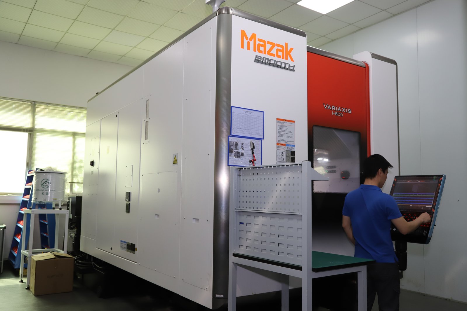
- 5-axis machining centres (10+) - Mazak VARIAXIS I-600 (510/910/510 mm travel, 12,000 rpm, 22 kW, 71.6 N·m, 30-tool BT40) and Mazak INTEGREX I-250H S (B-axis 0.0001°, 24 kW, 124 N·m, 38-tool HSK-A63). Applied to compound-angle parts, single-setup multi-face prismatic work, and aerospace fittings where datum transfer loss is unacceptable.
- 3-axis / 4-axis machining centres (50+) - Brother SPEEDIO S500Z2N / S700Z2N (10,000 rpm, 14/21-tool ATC, 0.7 s tool-to-tool, Z-axis 2.2 G) and Mazak VCE-430A L / VCE-570C L (10,000 rpm, 118 N·m, 24-tool ATC). Applied to prismatic parts, plates, brackets, housings.
- 100+ production machines — Mazak / Brother / Tsugami / Star / Citizen class, across a 6,800 m² facility (3-axis 50+, 4-axis 20+, 5-axis 20+, 25+ lathes, 7+ grinders, 20+ inspection instruments).
- Measured, not claimed: ±0.002 mm, verified on Hexagon CMMs. Per-characteristic capability is Ppk ≥ 1.67 initial and Cpk ≥ 1.33 production (≥ 1.33 general). Reports name the feature, band, sample size, sigma method and window.
- Certified under ISO 9001:2015, IATF 16949:2016 (design excluded) and ISO 14001:2015 — Dongguan Zhuohang Ltd is the invoicing entity behind them.
- Order terms: MOQ 1 piece, lead times of roughly 3 / 7 / 30 days depending on complexity.
- Machine highlights - VARIAXIS I-600: one-setup multi-face 5-axis + MAZA-CHECK auto-calibration; INTEGREX I-250H S: DONE-IN-ONE mill-turn, B-axis 0.0001° + Ai thermal shield; SPEEDIO S500Z2N / S700Z2N: Z-axis 2.2 G + 0.7 s ATC; Swiss-type: guide-bush switchable + 0.1 µm resolution.
Tolerance bands held: ±0.003 mm on CNC milling, ±0.002 mm on CNC turning, ±0.002 mm on precision grinding and wire EDM. Capability indices: Ppk >= 1.67 initial on key characteristics; Cpk >= 1.33 ongoing in production.
Certifications: ISO 9001:2015 (116024/A/0001/UK/En), IATF 16949:2016 (131941/A/0001/SM/En, design clause 8.3 excluded - disclosed openly), ISO 14001:2015 (116024/B/0001/UK/En). Certificates are issued to Dongguan Zhuohang Ltd (USCC 91441900MA4UWT6X39, established 2005).
Service area: Austria, Belgium, the Czech Republic, Denmark, France, Germany, Greece, Hungary, Ireland, Italy, the Netherlands, Spain, Sweden and the United Kingdom in Europe; Brazil, Canada, Mexico and the United States in the Americas; China, Israel, Japan, Singapore and Sri Lanka in Asia; Australia and New Zealand in Oceania; and South Africa in Africa. Based in China, serving customers worldwide.
Contact: Felipe Iglesias, [email protected], +86 13126536955.
Ready to have your parts precision-milled?
Send your drawing to [email protected] or call +86 13126536955 for a design-for-manufacturing review and a quote.
Frequently Asked Questions
What tolerance does precision milling hold?
In short, CNC milling holds ±0.003 mm and precision grinding reaches ±0.002 mm. Critical dimensions are verified on Hexagon CMMs, and our SPC on a representative length feature shows Cpk 1.851 (one characteristic on one part, not a blanket capability claim) against a key-characteristic target of 1.67.
Why does surface finish matter as much as tolerance?
In short, A part can measure perfectly yet fail because its sealing face or bearing journal was left too rough. Surface finish controls friction, wear, sealing, and fatigue life, so a precision milling supplier has to control it rather than leave it to chance.
How do you hold a fine surface finish on a mill?
By pairing the right feed, speed, and cutter to each alloy, running on a rigid setup, and finishing with clean cutting passes instead of rubbing. Finish is verified with a surface profilometer, not judged by eye.
What ruins surface finish and accuracy during milling?
Vibration and chatter. When the tool or workpiece flexes, the cutter bounces off the material and leaves chatter marks while dimensions drift. Rigid workholding and short, stiff tooling stop this before it starts.
What do Ra and Rz measure, and which number does each surface need?
In short, Ra is the average roughness across a surface; Rz is the average peak-to-valley height over a sampling length. A sealing face might need Ra 0.8 µm while a cosmetic cover can sit at Ra 3.2 µm — the right number is set by what the surface does, not by a chart alone.
What is the minimum order quantity?
One piece. You can prototype, validate, and iterate before committing to volume, with lead times of roughly 3, 7, or 30 days depending on part complexity and the number of process steps.
Which materials can be precision milled?
Aluminum, stainless steel, brass, copper, titanium, and magnesium, plus engineering plastics. Each alloy machines differently, so feeds, speeds, and cutters are adjusted per material to keep finish and tolerance honest.
Are you certified?
Yes — ISO 9001:2015, IATF 16949:2016, and ISO 14001:2015, with certificate numbers you can verify with the registrar. IATF 16949 scope excludes product design under Clause 8.3.
Which design rules keep a precision part affordable?
In short, Add an internal corner radius, respect a minimum wall thickness near 1 mm, keep drilled holes under a depth-to-diameter ratio of about four to five, give threads roughly one-and-a-half diameters of engagement, and keep features reachable by a short, stiff cutter. Each rule cuts cost without cutting function.
What should I check on the quote before I commit?
In short, That it itemizes material by grade, lists process steps separately, reflects the tolerances and finish you asked for, states whether fixturing is amortized or billed once, shows quantity breaks, and clarifies inspection documentation and the shipping terms. A quote that rolls everything into one number is where surprise costs hide.
How do I get a quote?
Send your STEP or IGES model plus a toleranced 2D drawing to [email protected]. You receive a design-for-manufacturing review that flags surface-finish and workholding issues before cutting, along with a quote.
Do you use MIL-STD-105E or ANSI/ASQ Z1.4 sampling inspection?
In short, MIL-STD-105E is the U.S. military sampling inspection standard published in 1989; it specifies acceptable quality limit (AQL) sampling plans for lot-by-lot inspection.
Standards referenced on this page
- IATF 16949:2016 — Automotive quality management system standard
- ASTM E8/E8M-21 — Standard Test Methods for Tension Testing of Metallic Materials
- ISO 9001 — Quality management systems — Requirements